You can generate multi-level BOMs from your CAD system. Here’s how.
First of all, please ensure you have updated your CAD plugin(s). That’s important to take advantage of the new multi-level option for the CAD plugin.
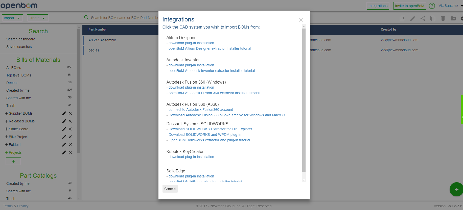
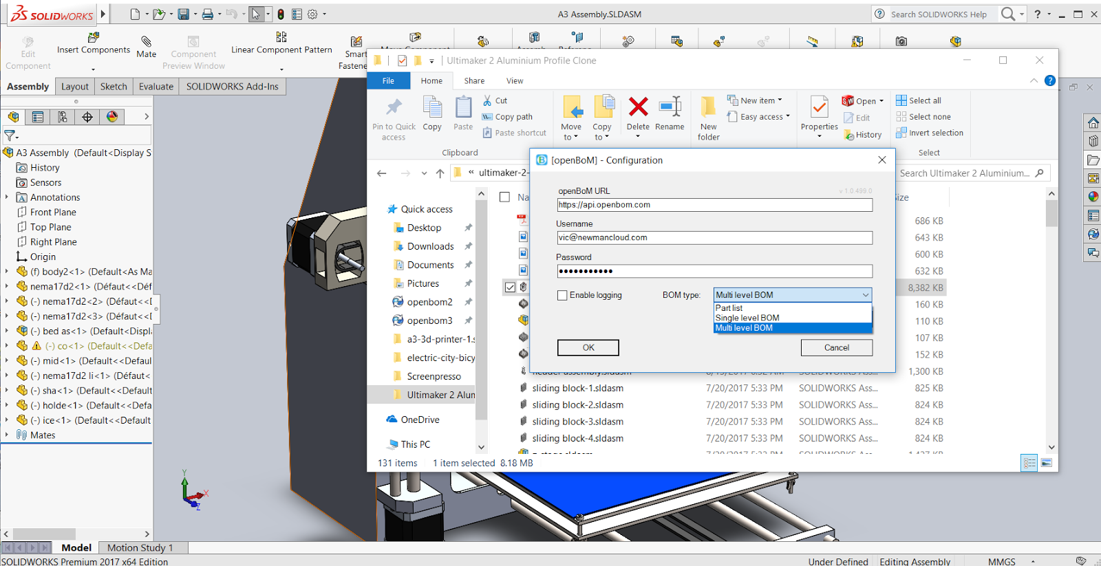
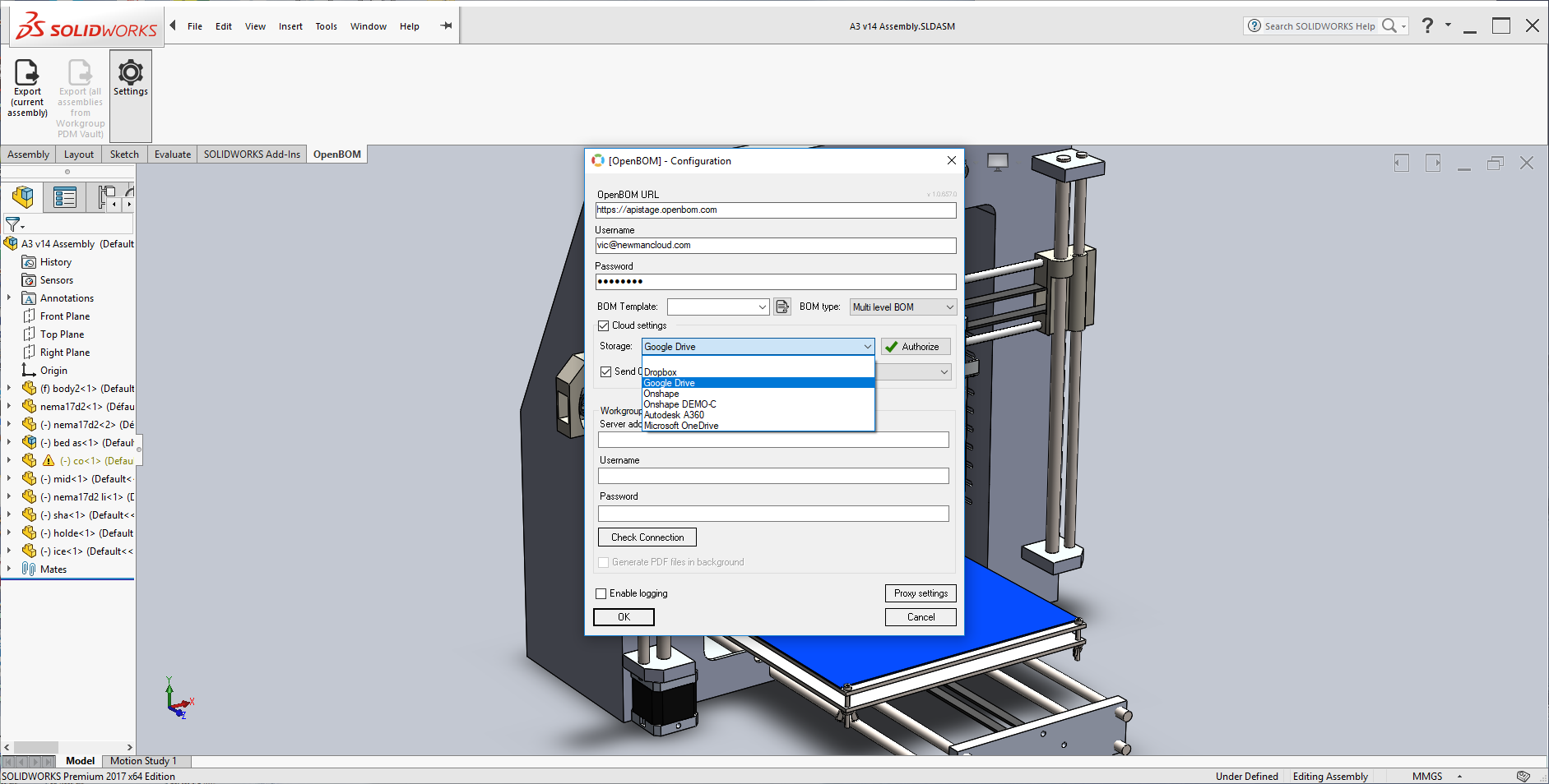
Read up on the full details for installing CAD plugins, here. In every plugin, you have the option to configure the kind of BOM you wish to generate. Make sure to select “Multi-level BOM” in Configuration.
Create Multi-level BOM from Windows File Explorer:
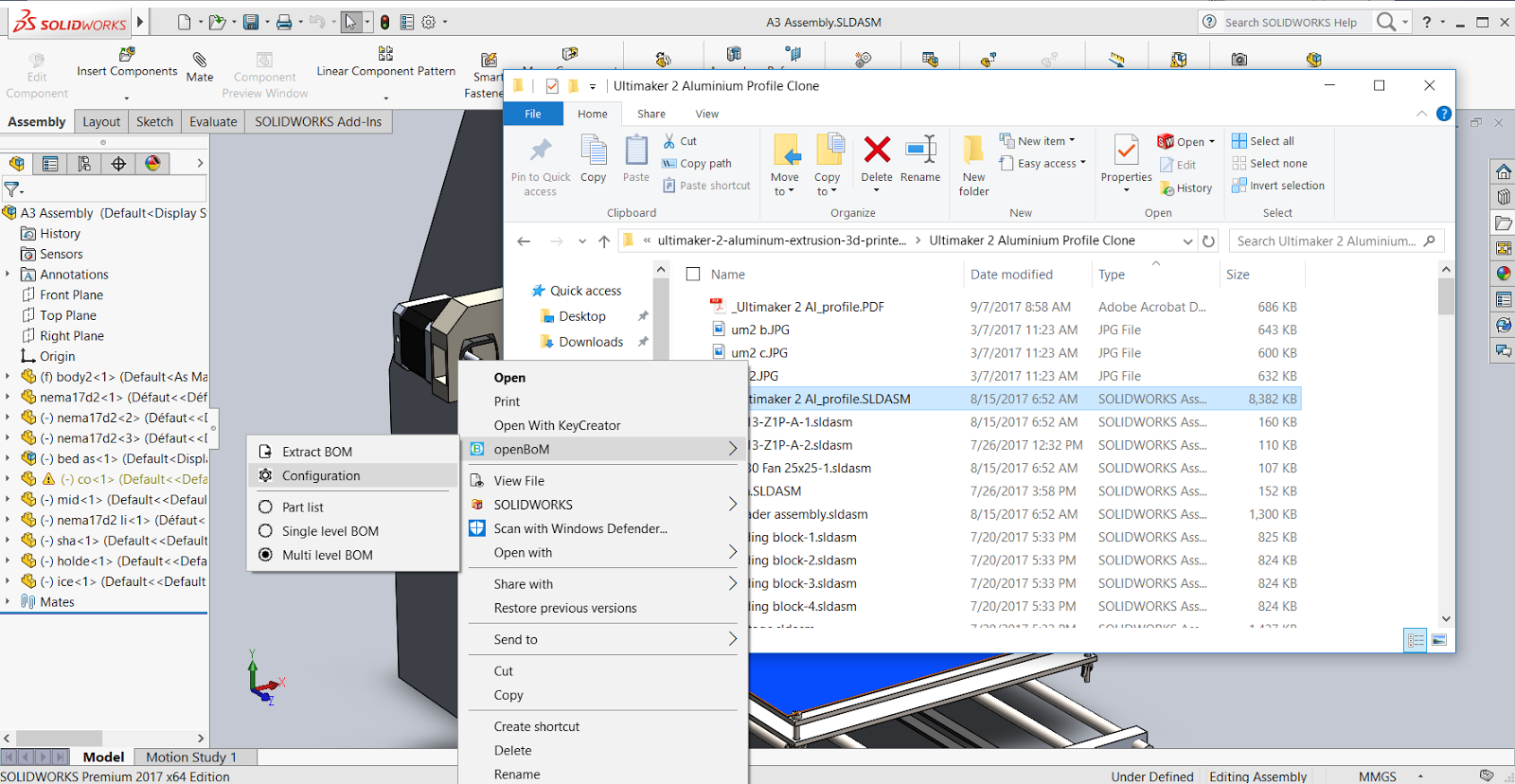
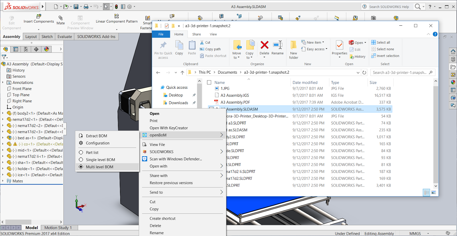
When ready to generate a BOM, choose the desired assembly and extract the BOM.
Create a Multi-level BOM from a file extractor plugin:

With this plugin, you’ll be able to connect CAD components in your BOM to external cloud file storage:
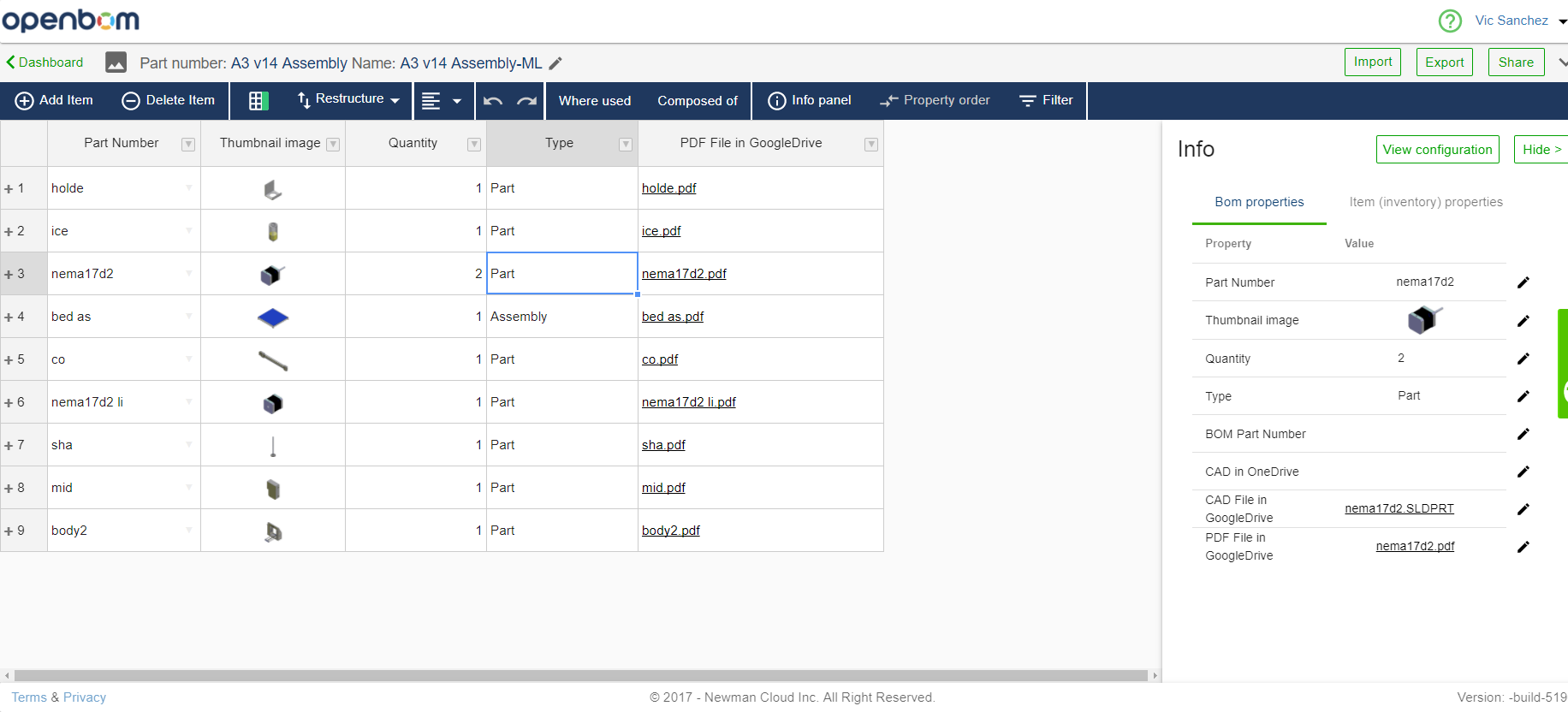
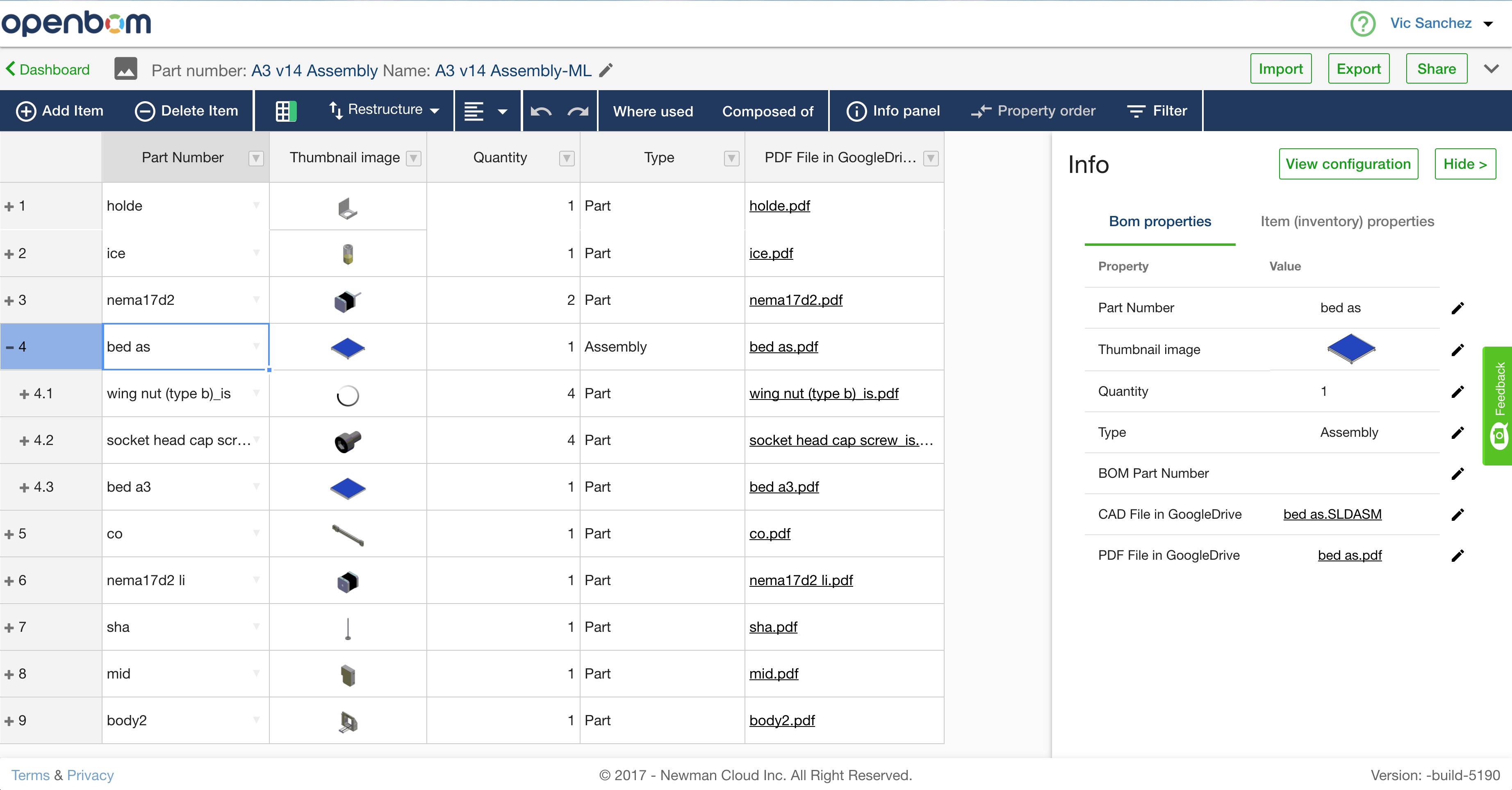
Here’s an example of what the BOM would look like with the connected cloud file storage:
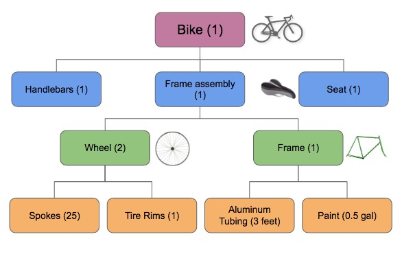
OpenBOM is now going to generate a multi-level BOM. Remember, make sure to choose the top level assembly to generate the BOM to ensure you capture all sub-assemblies. So for example, in this simple schematic, you’d choose the Bike assembly. All other sub-assemblies will also be extracted to generate the multi-level BOM.
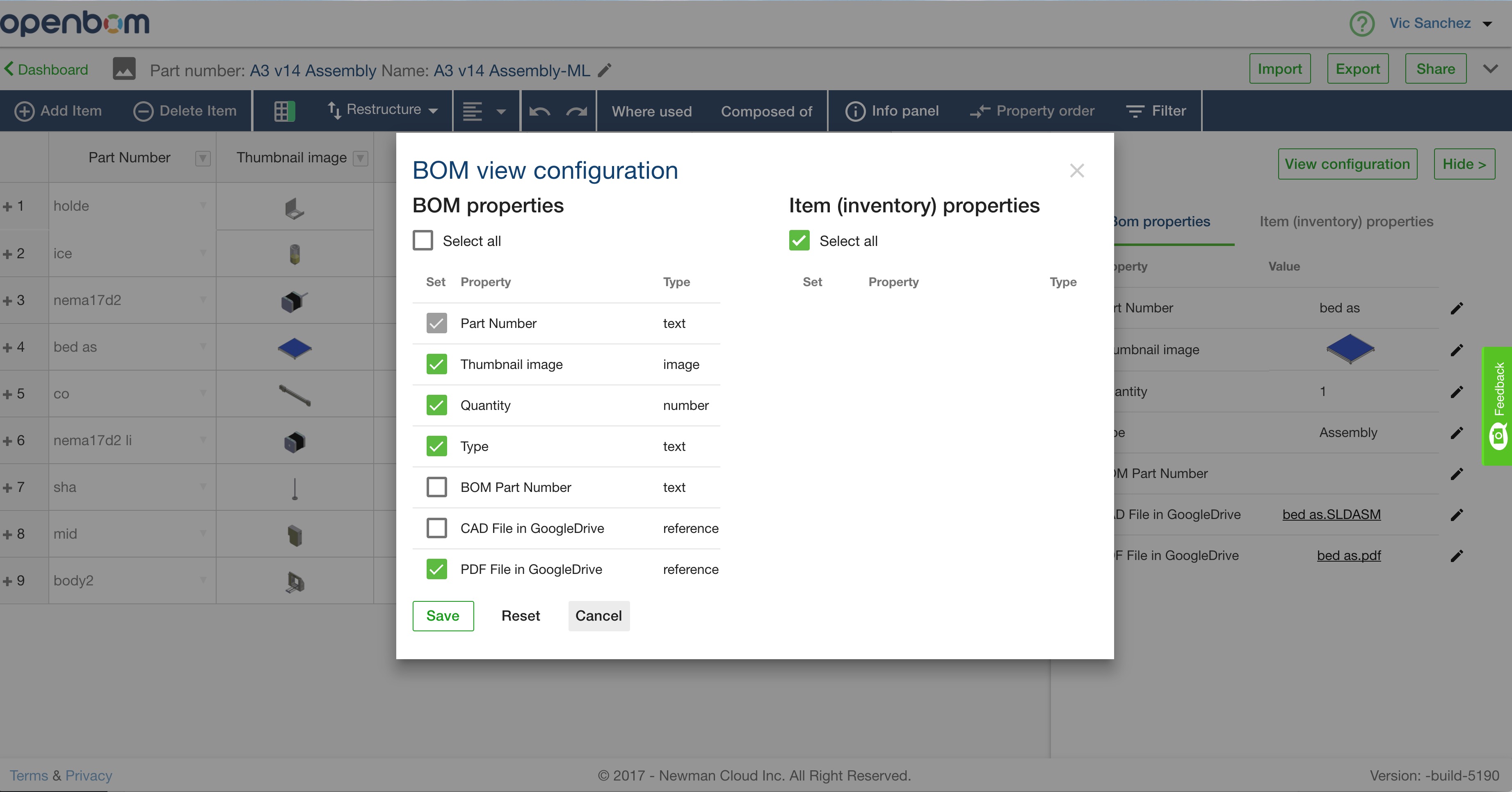
After the BOM is generated, you can access the Multi-level BOM view configuration by clicking “Info Panel” on the dark-blue panel and then click “View configuration” in the Info panel. The purpose of this is to set what BOM properties you want to be visible on the grid. OpenBOM is flexible and gives you the ability to configure multiple visible properties.
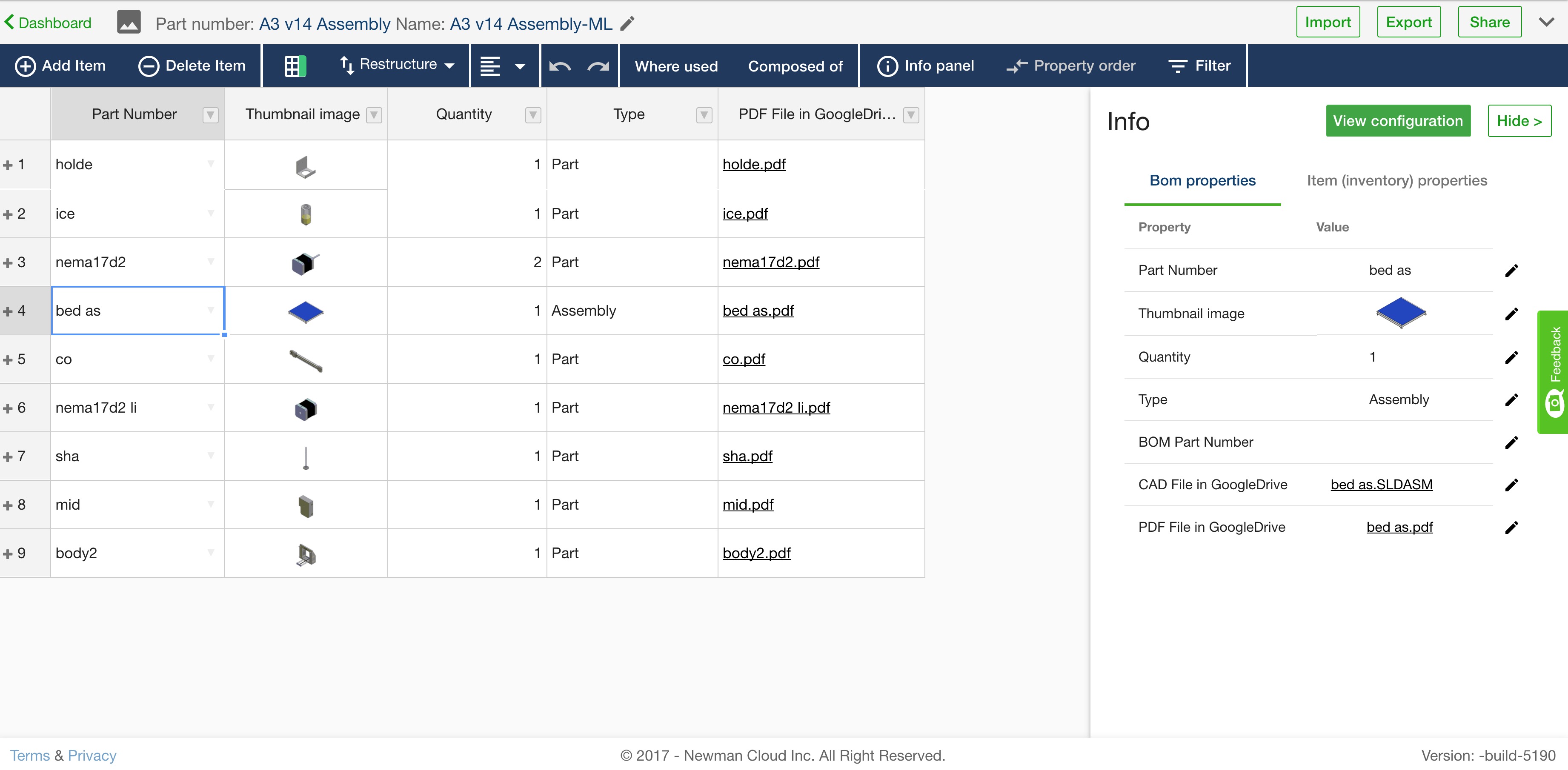
You can view the BOM and navigate to sub-assemblies.
If you are in the OpenBOM Dashboard, you can use the toolbar to open a multi-level BOM.
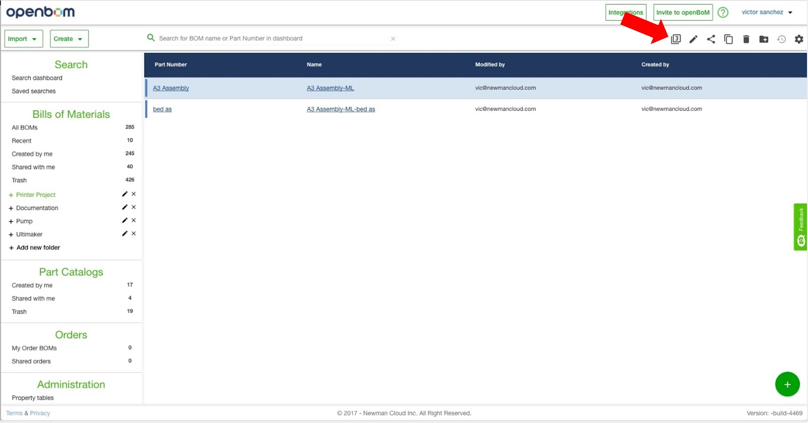
The multi-level BOM command will open a BOM for browsing multiple levels. All you’re just interested in viewing a single level BOM, click on the desired BOM in the Dashboard.
Depending on the number of sub-assemblies in your BOM, you may be wondering why you see so many BOM were extracted and placed in your Dashboard. Here’s an example of a multi-level BOM with many sub-assemblies as it appears in the Dashboard following extraction from CAD:
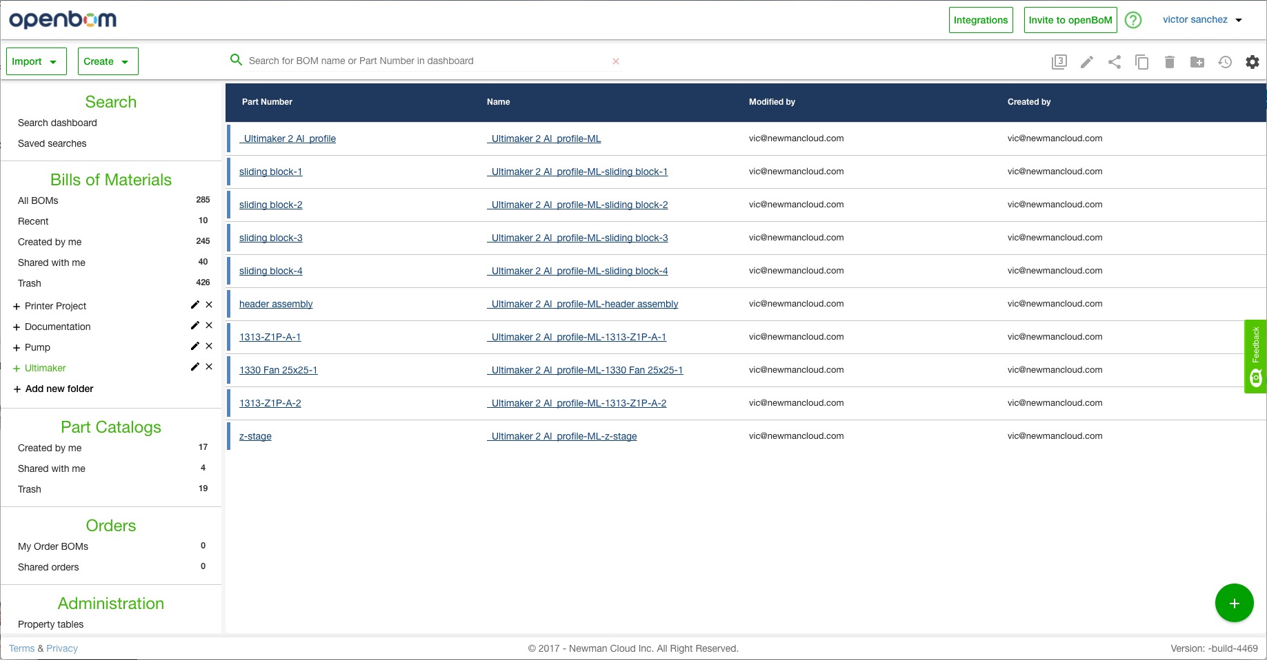
The reason is that each level of a multi-level BOM is represented by an independent BOM. There is a good reason we designed it that way and I will speak about that in another post. However, it’s clear we need to find a better way to see top-level BOMs and are working to improve in future releases.